Vertical ElectricalSounding (VES)
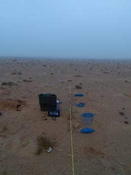
The vertical electrical sounding (or VES) method is used to investigate how resistivity varies with depth. This technique involves taking a series of resistivity measurements at progressively longer distances between current electrodes (A-B) and potential electrodes (M-N), within various types of quadripolar arrangements. Current is emitted into the land through both external electrodes A and B; the power difference generated in the subsoil as current flows between A and B is measured using two central electrodes, M and N. The power difference (ddp) and intensity of current (I) are used to obtain the true resistivity of the terrain.
By increasing the difference between the electrodes A-B and M-N, measurement can be extended to increasingly deep layers.
True resistivity curves are built by plotting true resistivity values on a bio-logarithmic diagram. A mathematical model is then used to obtain true resistivity value and the actual thickness of layers of different resistivity.
fields of applications:
Verification of presence or search for groundwater
Searching for water
Searching for hidden or buried cavities
Stratigraphic research
Geological modelling
2D - 3D ElectricalResistivity Tomography
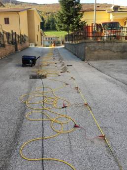
Multielectrode prospecting involves taking a number of apparent resistivity readings using quadripoles arranges along profiles, fitted with a certain number of electrodes (in general at least 48), usually equidistant along the investigation line, which can be controlled from a programmable georesistivity meter, so that operation can either take place when current is emitted (A, B) or when measuring potential (M, N).
Acquired data are processed using mathematical algorithms, to define two-dimensional electroresistive sections, in which resistivity variations can be highlighted, both vertically (as in VES) or along the investigation profile.
The use of special and complex electrode configurations installed in areas and not just along linear arrays, and the use of powerful software, means that 3D resistivity models of the subsoil can be obtained.
Verification of the presence of structural discontinuities (faults, sliding surfaces, etc.)
Verification of presence or search for groundwater
Study of pollution phenomena in the ground or beds
Searching for water
Definition of contaminated volumes
Searching for hidden or buried cavities
Stratigraphic research
Identification of underground utility leaks
Study of landslides
Geological modelling
2D - 3D InducedPolarisation Measurements
Induced polarisation is a type of multielectrode prospecting that is often associated with ERT investigations, as it enables the measurement of the capacitative component of terrain (known as Induced Polarisation), following the emission of electric current into it.
The physical parameter measured in the time domain is represented by apparent loadability, namely power loss along a discharge transient.
fields of applications:
Verification of presence or search for groundwater
Study of pollution phenomena in the ground or beds
Searching for water
Definition of contaminated volumes
Stratigraphic research
Arc Testing Method for theverification of HDPE sheets
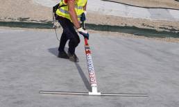
The Arc Testing Method is an electrical investigation methods used to locate “leaks” in exposed geomembranes, on the condition they are dry, clean and do not present excessive ripples, which may excessively shield the flow of current. It is based on the principle of creating high tension using a probe above the isolating membrane and electrode beyond the area of investigation, which closes the electric circuit if bores, holes, cuts or defects are present in welding.
Self-Potential Measurements
The Self-Potential method is a passive geoelectric type of investigation which involves the measurement of electric power variations in the subsoil, caused by an electrical field generated by natural sources (hydraulic, thermal and chemical), using a couple of non-polarizable electrodes. Spontaneous Potential components are mostly Electrokinetic Potential, generated by the flow of the aquifer, and Electrochemical Potential, generated by the difference of solute concentrates following redox reaction between water and rocks it comes into contact with.
OHMEX testingof HDPE sheet integrity
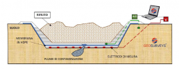
The OMHEX method is an electrical investigation method for the localisation of “leaks” in HDPE geomembranes buried by a water head or anthropic material. It is based on the principle of creating a flow of electric current between electrodes positioned in contact with the geomembrane and beyond the area under investigation; whenever there are bores, holes, cuts or defects in welding, the electric circuit is closed, or high power values are measured.
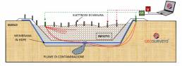
Installation and managementof fixed monitoring
A “Permanent Monitoring System” consists of a variable number of measurement electrodes immediately connected during initial phases of landfill construction under a HDPE sheet.
This system is connected to other electrodes, from which current is emitted, positioned both outside and inside the landfill basin, and above the geomembrane. Current is driven from the external electrodes to the Permanent Monitoring System, so that a series of anomalous power readings can be taken, attributable to the short-circuiting of current in the presence of any discontinuities. If integrity, and consequently electric insulation is guaranteed, no electricity flow will be present. However, if the sheet is damaged, electrical discharge can pass through any discontinuities.